Have you ever suffered a sudden disconnection of your WIFI or repeated reboots, but still unable to connect to internet with slow speed? The reason for these problems, apart from the router itself, it could be a problem with the fiber optic bend radius.
Fiber Optic Transmission Principles
Light transmission in optical fibers is mainly based on the principle of total reflection. When the light falls perpendicularly on the end face of the fiber and coincides with its axis, light propagates forward along the axis.
Nevertheless, if the fiber bends too much, part of the light does not propagate correctly, resulting in decreased optical power. This translates into a lower quality of the received light signal and slower Internet speeds..
Risks of Excessive Bending of Fiber Optic
Fiber Optic Cable Mechanical Properties
When the fiber bends, the external and internal zones are those that experience the greatest stress and where fractures are most likely to occur.
fiber optic fracture, including fracture caused by bending, is the result of a probability statistic. As the expected lifetime of the fiber increases and the length used increases, the probability of fiber break increases.
Therefore, in applications such as data centers or business rooms, where the useful life of fiber optic cables is much less than 25 years and the length of the fiber used is usually 1 km or even between a few meters and two hundred meters.
Optical Performance of Optical Fibers
In case of bending, it is easy to directly detect the bending loss of the fiber and visualize the change in optical power. Fiber optic loss under no-load bending can be more difficult to detect, but in similar bending situations, fiber loss under load shows a significant increase. This is mainly because the fiber is compressed internally., resulting in a loss of microbending.
Radiation Loss due to Bending of Fibers
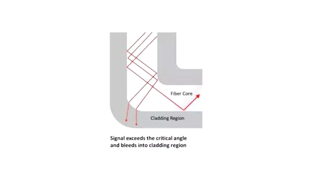
After the optical fibers are bent to a certain extent, though they can still guide the light, the light transmission path changes. A conversion from transmission mode to radiation mode occurs. This causes some of the light energy to enter the outer layer or to be lost out through the outer layer as radiation., resulting in a loss.
Nevertheless, when the fiber optic curvature radius is greater than 5 a 10 cm, loss caused by bending can be ignored.
Fiber Optic Curvature Radius
The bending radius of the optical fiber is the angle at which it can be safely bent at any given point.. All of the optical fibers or fiber optic patch cords have different bending radii. The minimum fiber optic bend radius of an optical fiber depends on the diameter and the type of fiber optic cable.
general formula: minimum bend radius = fiber optic cable outer diameter x fiber optic cable multiplier.
The new ANSI/TIA/EIA-568B.3 standard has defined standards for minimum bend radius and maximum pull for fiber optic cables of 50/125 microns and 62.5/125 microns. The minimum bending radius will depend on the specific fiber optic cable.
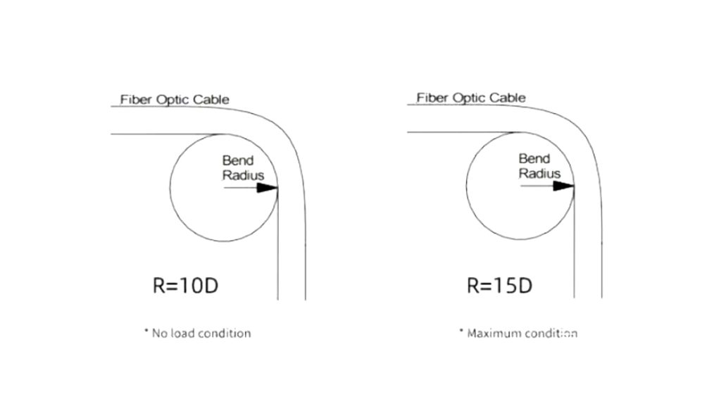
In the absence of tension, the bending radius of the fiber optic cable should generally not be less than ten times the outer diameter (FROM) fiber optic cable and 15 times the OD of the fiber optic cable when subjected to tensile loading.
Traditional industry standards for singlemode fiber optic patch cords typically specify a minimum bend radius of ten times the OD of the sheathed wire o 38 mm, depending on which is greater. Currently, commonly used G652 fiber has a minimum bend radius of 30 mm.
How To Reduce Loss Through The Structure Of Optical Cable
- Mode field diameter reduction: this layout is more intuitive, since the core is reduced and the refractive index of the core is increased so that the light beam can be better attached to the fiber.
- Reduction of the diameter of the outer layer: by reducing the fiber diameter, flexural strength is increased. As mentioned earlier, the fiber optic installation process requires paying attention to the size (for long term applications, the bending radius must exceed the 150 times the diameter of the outer layer of the fiber; for short term applications, and must exceed 100 times the diameter of the outer shell). Currently, the diameter of the bending resistant fiber has been reduced from 125 microns to 80 microns, and there are even fibers with an external diameter of 60 microns.
- Refractive index reduction of the outer layer
- Add a low index trench: In fact, this is somewhat similar to increasing the refractive index of the fiber core.
- Add a ring of symmetrical holes inside the outer shell: hole-assisted fiber (HAF) has a very different waveguide structure compared to chemically doped fibers. Although hole-assisted fiber (HAF) not sensitive to bending, the manufacturing cost of long-distance fiber is very high, and splicing is also relatively difficult, which is not compatible with existing mainstream standard devices.
- Nano-bubble assisted flex resistant fiber: this new fiber design (nanostructures) shows superior bending performance to meet fiber to home installation difficulties, and it is also relatively easy to mass produce and compatible with fusion splicing. This design consists of a core doped with normal germanium and an additional layer of nanostructured rings. (with bubbles ranging from a few nanometers to several hundred nanometers) inside the outer shell.
What to Do in Case of Fiber Optic Damage?
If you find that your fiber optic cable has been damaged due to a bend, you can contact your network operator and ask them to send a specialized technician to repair it. The repair process usually consists of the following steps.
- Confirm breakpoint location: Usually, the break point in the communication fiber optic cable can be located using detection equipment. Once the location of the break is determined, repair work can proceed.
- Temporarily connect the fiber optic cable: Once the location of the rupture is confirmed, fiber optic cable can be temporarily connected by connecting a temporary fiber optic cable. This will ensure that the communication network is not interrupted by a break in the fiber optic cable and will also allow time for repair work to be carried out..
- Fix breakpoint: For the breaking point in the communication fiber optic cable, should generally be peeled, clean and polish to prepare fracture. Then, a fiber fusion machine is used to fuse the fibers. When performing fiber fusion, it is necessary to ensure that the fiber inside the fiber optic cable is aligned with the center line of the fiber optic cable, and also pay attention to temperature control and fiber protection to ensure fiber quality.
- Verify the quality of the repair: After completing the repair work, it is necessary to use test equipment to verify the quality of the repair. This includes optical power tests, insertion loss tests and reflectance tests.
Resume
In summary, excessive bending of optical fibers can affect internet speed due to loss of optical power, radiation loss and fiber fracture. When selecting cables, oil and reliable fiber optic manufacturer. It is important to adhere to the recommended minimum bend radii and to take precautions when handling or installing fiber optic cables to avoid damage.. In case of fiber optic damage, the network operator can be contacted to carry out the necessary repairs.