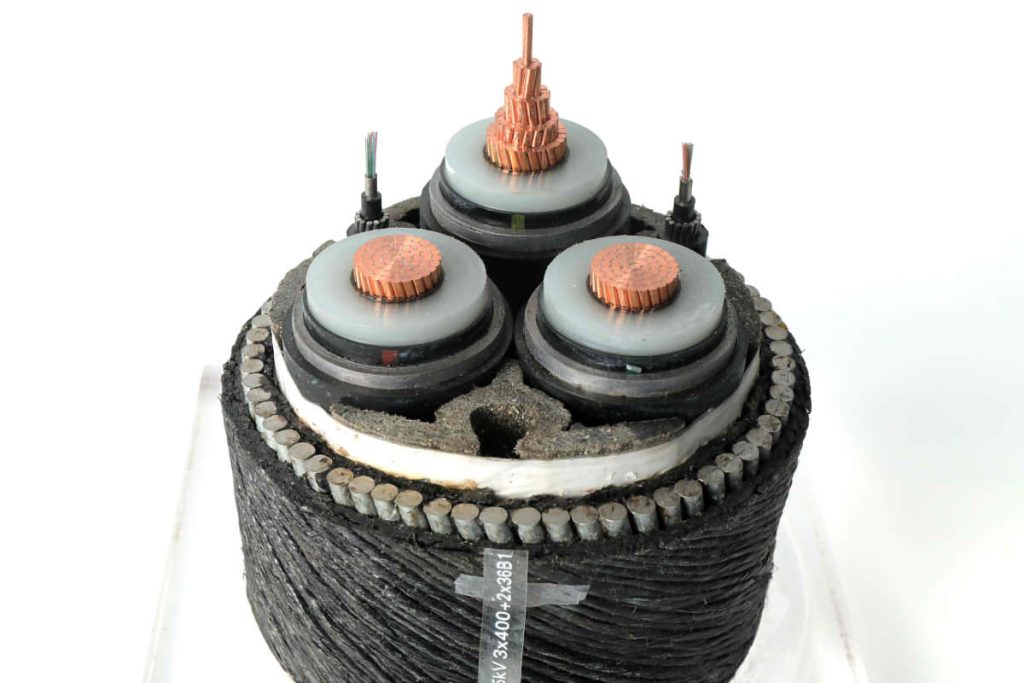
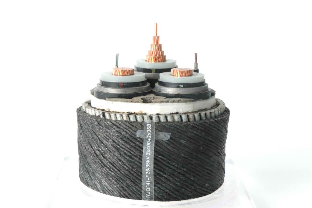
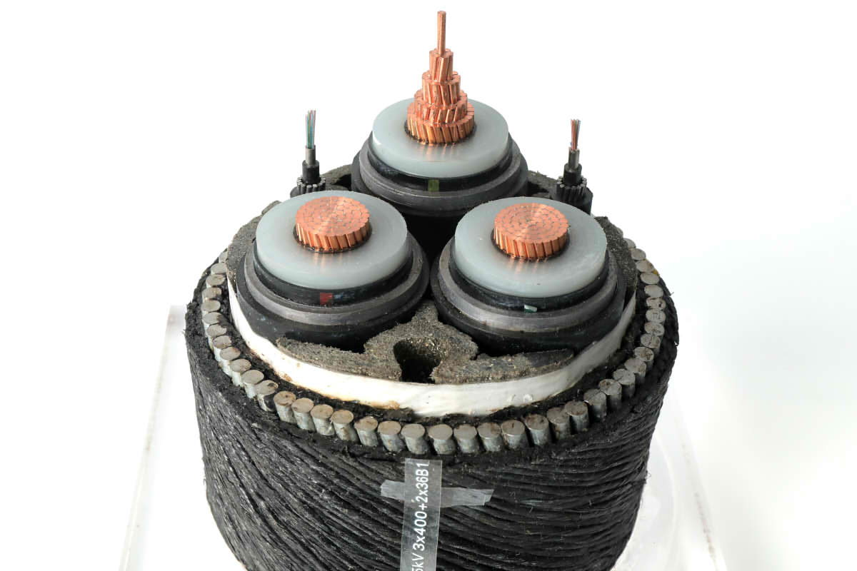
Submarine cables play a vital role in connecting coastal islands and cities around the world, allowing the transmission of electricity and data over long distances underwater. To meet the growing demand for power and signal transmission simultaneously, optoelectronic composite submarine cables have emerged. These technological advances are essential to maintain the constant flow of electricity and data in an increasingly interconnected world..

Investigation of the Water Resistance of Conductors
In the design of submarine cables, the water resistance of the conductors is essential. Cables must withstand extreme conditions of pressure and humidity at the bottom of the sea. International regulations set strict standards for water resistance testing of conductors.
Water resistance tests simulate water immersion at underwater depths. The cables must withstand this immersion for at least 10 days at a temperature equal to ambient, about 20 ℃ ± 15 ℃. Post-test visual inspection should demonstrate that no water has seeped into any part of the conductor..
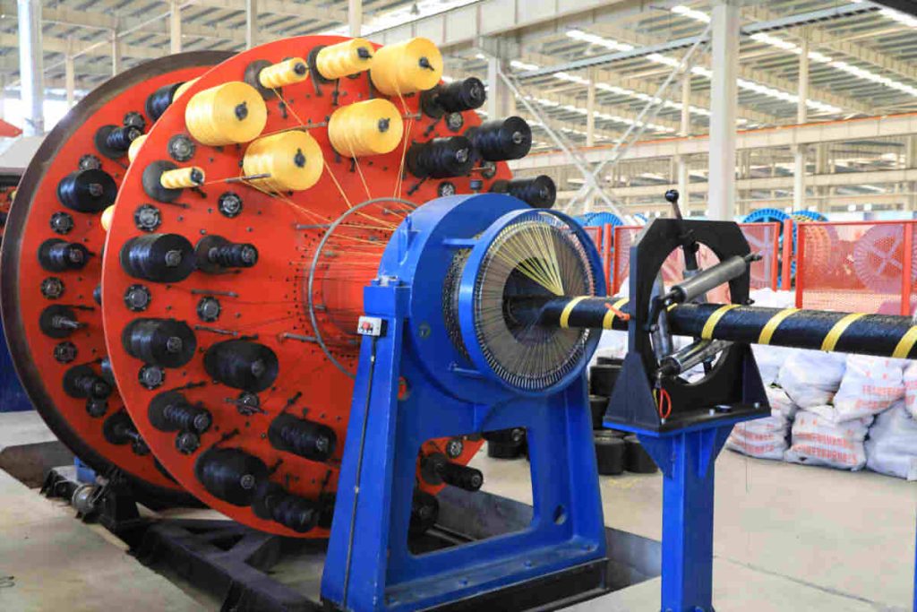
To improve water resistance, Tight circular pressure structure on conductors has been commonly adopted. Nevertheless, due to high tensions in the cables, the wire cross section size is large, which presents challenges in terms of water blocking. The solution lies in using multiple disc stranding machines (at least 91 discos) to reduce the diameter of individual conductors and, So, minimize the spaces between them, which improves the effectiveness of water blocking.
It is recommended to use a regular concentric stranding structure with water-blocking strands interspersed in each layer of the conductor.. This ensures effective water blocking and safe transmission.
Study of Cable Grounding
Grounding is a critical aspect in high voltage cables. For cables of 35kV or less, Two grounding points are used at both ends due to its three-core configuration. This minimizes the possibility of voltage induced in the metal shielding layer..
Nevertheless, for single core cables with voltages greater than 35kV, a challenge arises. The core of the cable behaves like the primary winding of a transformer, generating induced voltages in the metal shielding layer when carrying current. This may pose risks to the safety and integrity of the cable..
In such cases, Single point grounding on the metal shielding layer is recommended, with a limit of 50-100V for the induced voltage. For longer cables, additional methods may be considered, such as segmentation of the shielding layer or the use of intermediate insulation.
For long submarine cables and ultra high voltage, These standard practices may be insufficient due to induced voltage buildup.. Innovations are required to address this challenge, and some companies have made significant progress.
Research on Armor Layers of Composite Optical Cables
In optoelectronic composite submarine cables, Fiber optic cable units represent a critical component. The design must consider both the optical and mechanical properties of these units. To effectively protect fiber optic units, are placed on the steel wire layer, preventing the steel wire from applying direct pressure on them.
This provision protects fiber optic units from mechanical damage, ensuring reliable optical transmission in challenging underwater environments.
For single core cables, It is essential to select non-magnetic materials for the armor layer in alternating current system environments. In underwater applications, The reinforced layer must be corrosion resistant and have sufficient tensile strength. Stainless steel wire is considered a preferable option for cable armor. Nevertheless, in cases where a balance between costs and performance is sought, galvanized steel wires can be used together with magnetic insulation structure.
Armor layer design should be based on actual current capacity required to ensure optimal performance.
Investigation of Production Equipment for Long Cables

Production of long submarine cables, seamless, It's a significant challenge.. The ability of equipment to receive and release large tonnage cables without interruptions is a critical aspect. This is because the length of cables such as 110kV 1 × 500 can easily cover several kilometers, which makes it difficult to manipulate in one piece.
Currently, Submarine cable jointing technology has become increasingly mature and is widely used to overcome these limitations..
Las submarine cable manufacturing companies are exploring solutions to improve the production of long cables. This involves not only the capacity of production equipment but also internal logistics and other key factors..
Cable Testing Research
Testing long submarine cables is challenging due to the difficulty of transporting these long cables.. Power supply systems for cable testing must be lightweight and transportable to the storage site.
It is recommended to use a resonant power supply system with an output voltage of at least 320kV and a frequency range of 30-300Hz. Nevertheless, due to the length of the cables, The capacity of cable testing equipment may not be enough. In such cases, Sampling can be done on finished cables to measure the partial downloads as an indicator of the electrical properties of the cable.

Conclusion
Advances in the design and development of optoelectronic composite submarine cables are essential for the expansion of communications networks and long-distance electricity transmission.. Water resistance of conductors, grounding of high voltage cables, research on composite optical cables, shielding layers and production equipment are critical areas of research that have led to significant improvements in submarine cable technology.
These advances not only guarantee the reliability of underwater networks, but also enable efficient transmission of power and data in challenging marine environments, thus promoting global connectivity. The future of optoelectronic composite submarine cables is promising as technological evolution in this field continues.

