Fiber optic communication uses light waves as carriers and optical fibers as transmission media to send signals from one place to another.. The use of optical cables with fiber optics in power transmission lines, from 35kV overhead lines to high voltage lines, is an important direction in the development of specialized power optical cables. With the expansion of electrical system communication networks, The use of OPGW fiber optic cables in power transmission lines has become common.
Table of Contents
- What is OPGW Optical Cable?
- Design of OPGW Communication Lines
- Lightning Protection for OPGW Cables
- Mechanics of OPGW Optical Fibers
- Vibration Prevention Measures for OPGW Cables
- Layout of OPGW Overhead Cables
- OPGW Installation Tips
- Conclusion
What is OPGW Optical Cable?
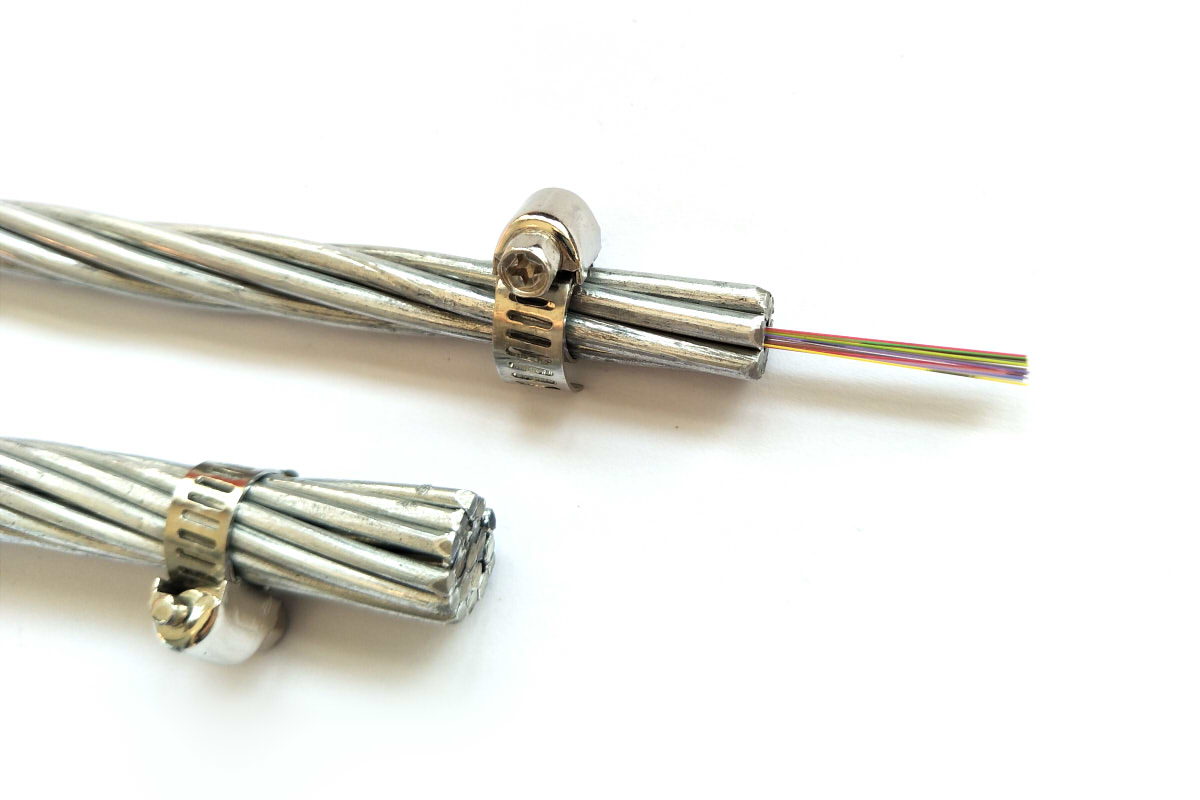
OPGW fiber optic is a new generation ground cable structure that combines composite optical fibers with high voltage transmission cables.. It has the dual function of a conventional ground wire and a communication cable.

The OPGW is an emerging information transmission channel that has experienced rapid development in recent years.. It is characterized by its communication skills, interference resistance, security and reliability, and does not take up space in the line corridor. Besides, skillfully combines fiber optic communication cables with high voltage transmission cables in a single structure. Its excellent mechanical and conductivity properties not only meet the lightning protection requirements of a conventional ground cable, but also, due to its excellent conductivity and shielding effect, significantly reduce electromagnetic risks to nearby power lines.
Structure of OPGW
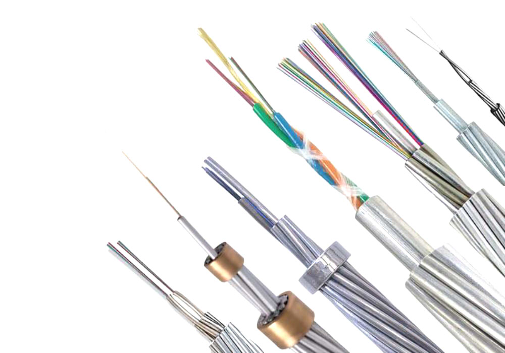
The OPGW cable is classified according to the components and structure of OPGW cables., as follows:
- Depending on the material of the protection tube of fiber optic units, OPGW is divided into OPGW with stainless steel tube and OPGW with aluminum tube.
- Depending on the position of the fiber optic units in the OPGW structure, it's divided in Center Tube Structure OPGW and interlaced layer structure OPGW.
- For OPGW with stainless steel tube, It is classified into OPGW from a single fiber optic unit, OPGW of two fiber optic units and OPGW of multiple fiber optic units according to the number of fiber optic units.
- According to the material of the interlocking layers and the lines of interlocking layers, OPGW structure is divided into full aluminum structure with steel (all interlocking ply lines are aluminum with steel) and mixed structure (Interlocking layer lines include aluminum with steel and alloyed aluminum).
OPGW Standards
Current standards for OPGW optical fibers in overhead lines include:
IEEE 1138-2009: Composite fiber optic cable construction standard for overhead power lines.
IEC 60794-4-2003: Part 4-1 the IEC 60794: Combined specifications for fiber optic cables for electrical transmission lines.
GB/T 7424.4-2003: Part 4 from GB/T 7424: Specifications for optical cables with composite optical fibers for overhead lines.
DL/T 832-2016: Optical cable with composite fiber optic.
JB/T 8999-2014: Optical cable with composite fiber optic.
Design of OPGW Communication Lines
In general, OPGW cable models are proposed by electrical professionals specialized in transmission lines. In the field of line communications protection, The use of ground cables with a larger section and lower resistance is proposed to improve the short-circuit current dissipation capacity of the ground cable., thus preventing the OPGW from being damaged by short circuit currents. When a short circuit to ground in a phase of the line, the ground wire must withstand a significant short circuit current, which causes an increase in temperature in the cable. To avoid a significant decrease in the mechanical resistance of the ground wire, the temperature rise must not exceed the permitted values.
The allowable temperature for thermal stability verification of ground cables is set at 200°C for aluminum stranded cables with steel core and alloy steel stranded cables with steel core., 300°C for steel-coated aluminum stranded cables, 400°C for galvanized steel stranded cables and, usually, 200°C for OPGW aerial cables. When a short circuit occurs near a terminal tower, the short circuit current flowing through the ground wire is maximum.
Based on design experience, The short circuit current flowing through the ground wire from the entrance tower to the ground usually represents about 15-20%, while the short circuit current flowing through the ground wire is usually 80-85%. In conservative calculations, It can be considered that the 90%-95% of the short circuit current flows through the ground wire for calculation.
Lightning Protection for OPGW Cables
The damage caused by lightning to OPGW optical fibers is similar to the damage caused to overhead conductors. Mainly, manifest as melting points or fusion breaks in the outer layers of cables after being struck by lightning. Currently, Most cases of OPGW cable breakage occur in the outer layers of aluminum alloy and, to a lesser extent, in aluminum clad steel cables due to lightning strikes. The phenomena of breakage of OPGW cables due to lightning strikes can be classified into two categories.:
(1) Direct fusion of cables during high temperature electric arc process, resulting in a ball shaped break in the cable.
(2) After high temperature electric arc, the cables are in a molten state, which significantly decreases its mechanical properties, and break irregularly under the influence of external forces.
To improve the lightning resistance of OPGW cables, The following measures can be taken:
Installation of OPGW fiber optic cables
When selecting the route of the high voltage transmission lines, surrounding mountainous areas with frequent electrical activity should be avoided, areas with pronounced slope changes, areas with underlying metallic mineral deposits and areas near ponds. This will reduce the likelihood of lightning strikes on transmission lines..
Reduce the ground resistance of high voltage transmission towers to increase the lightning resistance of transmission lines. In a range of 1-2 km from the input and output substations of the transmission lines, The ground resistance of the towers must not exceed 10Ω, while in other sections of the line it should not exceed 30Ω. This primary approach seeks to reduce the short circuit current passing through the OPGW cable., and in some cases, The ground connection of the first tower is connected to the ground network of the substation.
OPGW Product Selection
Use high-conductivity ground wires that match OPGW cables or increase the cross-section of ground wires to improve the dissipation coefficient of high-conductivity ground wires and reduce the lightning current passing through OPGW cables..
In compliance with the coordination requirements of high resistance ground wires with a value of S≥0.012L+1 and the loading conditions of towers, choose large cross-section OPGW cables with multi-layer structure as far as possible, avoiding single layer structure OPGW cables.
Design of OPGW cables
Design an air gap between the outer and inner stranded strands of OPGW cables to allow rapid dispersion of heat generated by lightning strikes, delaying the spread of heat to internal threads and optical fibers, avoiding overheating and breakage of the central fiber.
The outer layer of OPGW cables is mainly composed of aluminum alloy wires (AA) and aluminum clad steel cables (AS). Los aluminum clad steel cables They have good conductivity properties, with melting points and mechanical resistance higher than those of aluminum alloy wires. Therefore, Using aluminum clad steel cables in the outer layer of OPGW cables generally contributes to improving the lightning resistance of OPGW and reduces the probability of breakage due to lightning strikes..
For OPGW composite ground cables of power lines 110 kV or lower, Aluminum clad steel wires with a single diameter of 2.8 mm or more. For lines of 220 kV or higher, Aluminum clad steel wires with a single diameter of 3.0 mm or more. And strict regulation of the construction process must be followed.
Mechanics of OPGW Optical Fibers
Calculations of mechanical properties of composite ground cables with optical fibers (OPGW) are similar to overhead and ground cable calculations. The arc deflection characteristics of the ground wires and OPGW must match the design characteristics of the OPGW. Although a working condition is not specified, an annual average operating scenario is generally considered (a +15°C, no wind) during design.
The design safety factor of OPGW cable fiber optic for aerial laying must be greater than 2.5 and should not be less than the design safety factor of the conductor. The safety factor at the suspension points must be greater than 2.25. In rare windy or icy weather conditions, The maximum tension at the OPGW suspension points must not exceed the 66% nominal breaking strength.
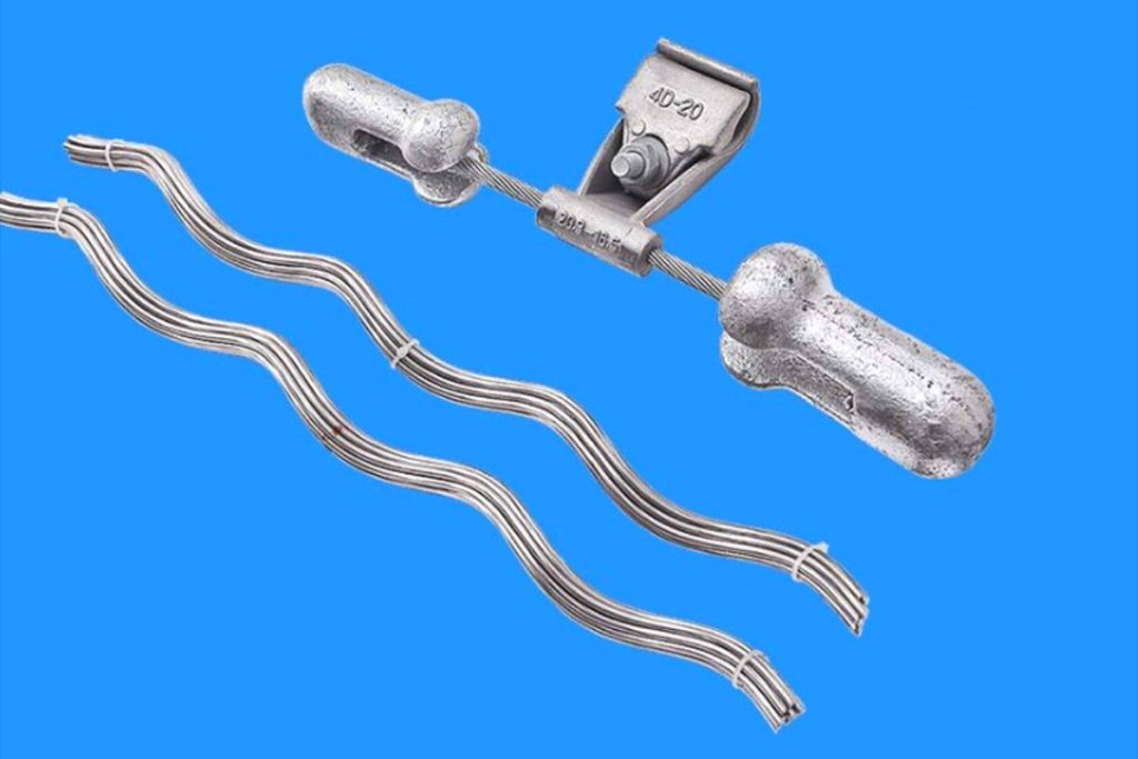
Vibration Prevention Measures for OPGW Cables
The average operating voltage of the OPGW must not exceed the 20% nominal breaking strength, and appropriate vibration prevention measures must be taken according to the upper limit of the annual average operating voltage. In lines with diameters of 20 mm or more, as well as on lines with large spans, vibration prevention measures must be taken, such as the use of shock absorbers, based on operational experience.
Layout of OPGW Overhead Cables
OPGW cable layout length should consider construction factors, operation and maintenance. Layout length calculation must take into account the actual length of the OPGW, the length of cable used in construction, the length of downstream cable on both sides and the fusion length of the fiber optic cable. In general, an arrangement length of 3 a 4 km. In calculating the layout length, The length of descending cable on both sides is determined according to the height of the tower at the splicing point of the fiber optic cable. And the fusion length of fiber optic cable is usually 10 m.
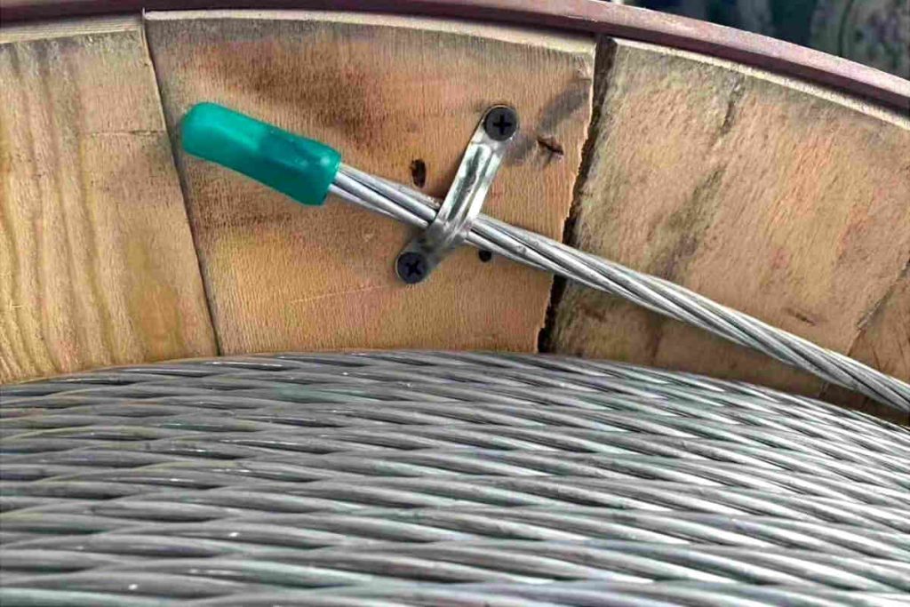
OPGW Installation Tips
The arrangement of OPGW cables should be straight and aesthetically pleasing, with a fixed support installed each 1.5 m a 2 m to prevent the cable from coming into contact with the towers and causing friction. The down cable between the structures in the station must be fixed with suitable clamps and rubber insulators, maintaining a distance of at least 20 mm between downcable and structural components.
Las OPGW cable junction boxes Fiber optic cables must be installed at a minimum height of 5 m above the ground. For special fiber optic cables, It is recommended to install a clamp every 2 m to fix the descending cable, and the minimum allowable bending radius of the drop cable must meet the product requirements.
Using spot grounding or a complete isolation system for the OPGW can significantly reduce energy losses.. Although the use of completely or segmentally insulated ground lines or OPGW in combination with high conductivity ground lines reduces the induced current in the ground lines or OPGW, can significantly increase the voltage induced in the lines, which entails risks in the operation and maintenance of the line.
Conclusion
OPGW optical cable is an impressive example of the convergence of technologies to meet the growing demands of communication and power transmission. Its advanced design and features make it highly efficient and reliable. Lightning protection and vibration prevention measures ensure optimal performance, and its careful installation on high voltage lines is essential. OPGW has become an essential component in electrical and data transmission infrastructure, playing a key role in the modernization of energy and communication networks.